Building a DIY 6-DOF Robotic Arm
2026-03-06I have been building an application that runs on top of industrial robotic arms. I needed a physical platform to validate motion control and kinematics in real time on actual hardware. Procurement of a commercial 6-DOF arm is expensive. I wanted an affordable way to test my ideas before committing to expensive industrial hardware. Purchasing an educational robotic arm was also not viable for me, as I was on a tight budget after quitting my job. I decided to build a low-cost desk-sized robotic arm prototype that could be used as a base platform for experimentation and validation of various ideas.
This post documents the design decisions, mechanical structure, and electronics architecture of this prototype arm.
Design Goals
The design goals are • 6-DOF articulated arm that could sit on my desk and allow me to validate kinematics, motion planning, and control software. • Low cost (< ₹80,000/$900) • Modular joints for easy modification • Capable of running industrial-style control software
Why a Desk Arm?
Cost — A full industrial robot arm costs 50–100× more than this setup. So far I have spent approximately $800 (~₹73,000 INR).
The largest expense was the Creality Ender 3 V3 KE 3D printer (~$325 / ₹30,000).Availability — The arm sits on my desk, allowing me to test anytime and validate various POC ideas.
Goal — Build a desk arm with ±1–2 mm repeatability in the first version.
Design Overview
The arm is based on the open-source AR4 platform by Chris Annin, with several modifications to accommodate our motor choice and design constraints.
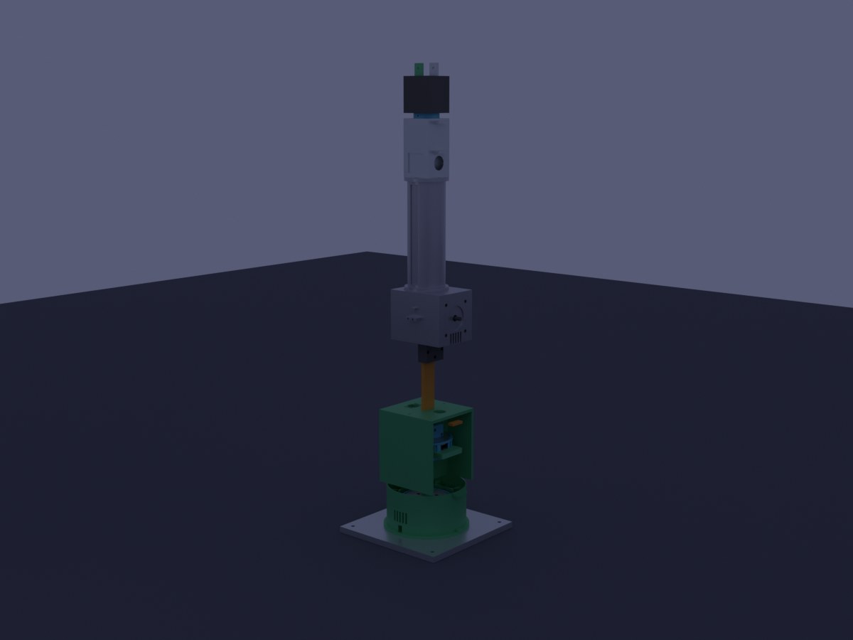
Complete CAD assembly: base plate, cycloidal drives (J1–J3), shoulder, upper arm, elbow, forearm, and wrist with gripper.
Specifications
| Parameter | Value |
|---|---|
| Degrees of Freedom | 6 |
| Reach | ~420 mm |
| Payload | 500 g – 1 kg |
| Repeatability | ±1–2 mm |
| Total Weight | ~7.9 kg |
| Total Height (home) | 673 mm |
| Frame Material | 3D printed PETG + aluminum base plate |
Architecture
The arm follows the classical articulated robot configuration:
J1 – Base rotation
J2 – Shoulder
J3 – Elbow
J4 – Wrist roll
J5 – Wrist pitch
J6 – Wrist yaw
The arm can be divided into two mechanical regimes.
Joints 1–3 (Base, Shoulder, Elbow)
These joints carry the full weight of the arm and payload.
They use closed-loop NEMA23 stepper motors (Endox 57EX22-ED) with cycloidal gear reduction (15:1 and 20:1 ratios).
Closed-loop stepper motors use an encoder to detect missed steps and automatically correct them. This significantly improves reliability and positional accuracy under load.
Joints 4–6 (Wrist)
These joints only move the wrist and gripper, so the torque requirements are much lower.
They use open-loop NEMA17 stepper motors with GT2 belt reduction (3:1). Belt drives are lightweight, simple, and sufficient for the lower loads of the wrist assembly.
| Joint | Function | Motor | Reduction | Category |
|---|---|---|---|---|
| J1 | Base Rotation | NEMA23 (closed-loop) | 15:1 Cycloidal | Heavy |
| J2 | Shoulder | NEMA23 (closed-loop) | 20:1 Cycloidal | Heavy |
| J3 | Elbow | NEMA23 (closed-loop) | 15:1 Cycloidal | Heavy |
| J4 | Forearm Roll | NEMA17 | 3:1 GT2 Belt | Light |
| J5 | Wrist Pitch | NEMA17 | 3:1 GT2 Belt | Light |
| J6 | Wrist Roll | NEMA17 | 3:1 GT2 Belt | Light |
Why Cycloidal Gears?
One of the key design decisions was using cycloidal gear reducers for the main joints.
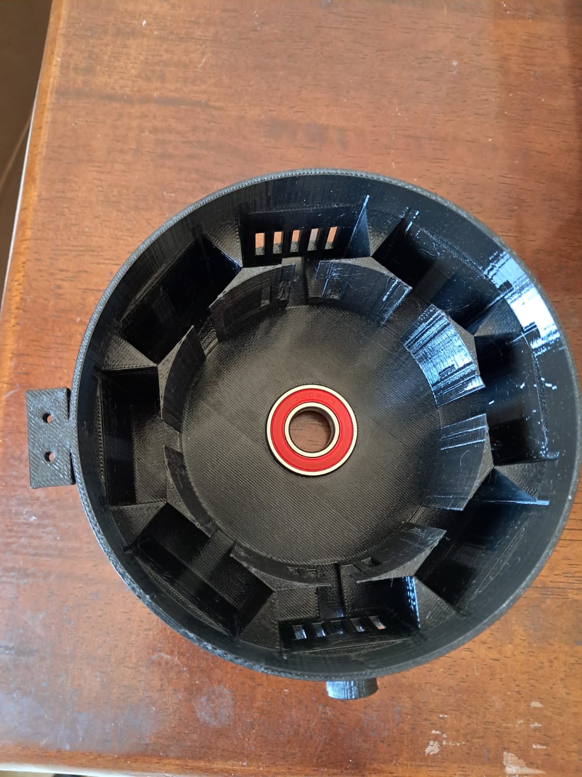
Compactness — The planned cycloidal drive fits inside an 80–95 mm diameter housing, making it suitable for a compact desk robot.
Load distribution — The forces are distributed across multiple contact points rather than a single gear tooth. This reduces wear and improves durability.
Smooth operation — Cycloidal reducers tend to have lower backlash and smoother motion compared to simple spur gear reductions.
Lessons Learned
Working under a tight budget meant minimizing wasted prints and planning carefully before manufacturing parts. One early issue was tolerance management in 3D printed components. Even though I added clearance in the design, the fit was still too loose. The 14.1 mm eccentric cam did not fit correctly into the HK1412 needle bearing. The solution was to reprint the part with an additional 0.4 mm offset and then carefully sand the part to achieve the correct press fit.
Another lesson was to procure SMPS, motors,driver and other electronic components before printing structural parts.. Stepper motors vary slightly in length depending on the model, and the housing needs to be re-designed accordingly, due to unavailability of planned parts and i have to switch to a different model, causing a reprint of 3d parts.
Another problem i encountered early in the design was that the Endox motors have an 8 mm shaft, while the cycloidal eccentric cam had a 6 mm bore. Boring the cam to 8 mm would leave dangerously thin walls, weakening the component. The solution was to use a clamp coupler (8 mm → 6 mm). The coupler connects the motor shaft to a 6 mm steel stub shaft (6 mm × 40 mm with D-flat). The eccentric cam then mounts on the 6 mm shaft, leaving a safe wall thickness of ~1.8 mm.
The base housing took almost 17hours to print and the wall planned for the ventilation was too thin and broken immediately after printing. it takes a good amount of time to workout on the design , print settings and tolerance levels.
I initially planned to integrate the 48 V SMPS power supply inside the robot base. However, the available space was insufficient. The design was updated to use a separate control cabinet, which will house:
- power supply
- motor drivers
- control electronics
Separating the electronics from the robot base also improves cooling, serviceability, and cable management.
i will be posting more articles on building the robotic arm as it is being built.